Making progress on my pedal steel

For people who build steel guitars

Moderator: J D Sauser

Post Reply
Javier Schulenburg
Posts: 17
Joined: 15 Feb 2022 2:50 pm
Location: Austria

Making progress on my pedal steel

Post by Javier Schulenburg »

Hi everyone!

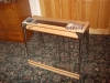
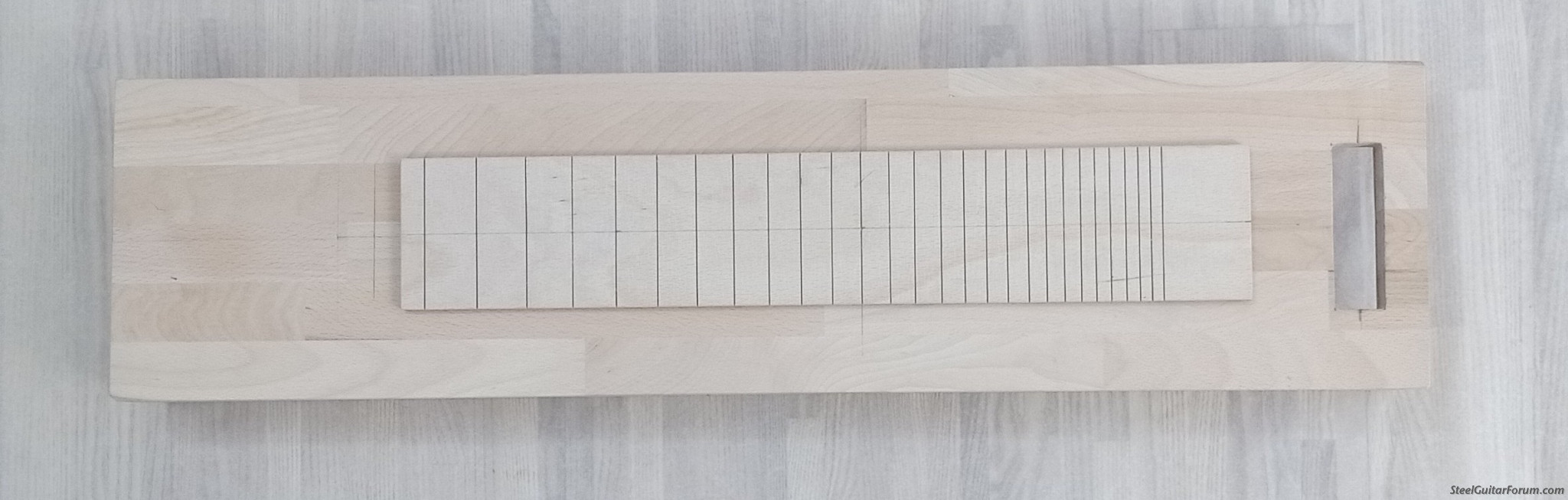
Since over a year I have been meaning to start building a pedal steel guitar. After some failed attempts at an all-pull changer I've settled on making a Steel with a Pull-Release changer which is the most reasonably doable as soon as I get some suitable pieces of Aluminum to make the actual changer. Nonetheless, I've decided to start by making a glued panel beech (18mm thick) body measuring 80x20x8.8cm with beech ply fingerboard

Image


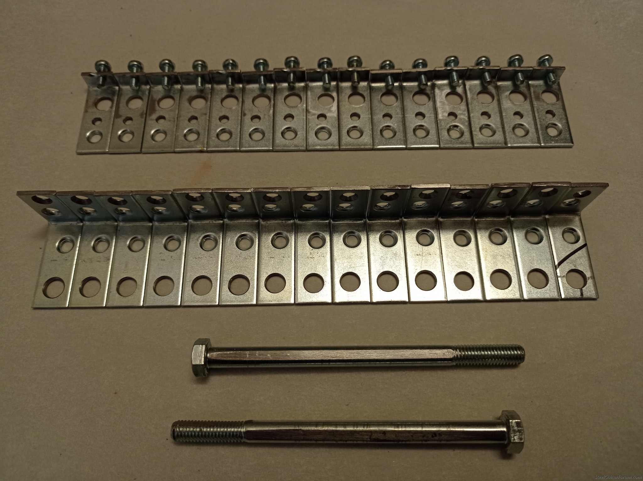
And making the most simple bell-cranks (pictured at the top) and holders for the cross bars (pictured at the bottom) from some 2mm thick galvanized steel corner pieces for chairs and using M8x120 bolts for the cross bars
Image


The pull/release rods will be 3mm steel welding rods which turned out to be very easy to thread by hand

The tuning will be a 3x4 E9 10 string with Nashville tuning or a modification thereof. I will add to this during the coming months or so as I slowly progress. Feel free to correct me on my vocabulary

Cheers,

Javier Schulenburg
Last edited by Javier Schulenburg on 10 Oct 2024 9:34 am, edited 4 times in total.
John Hyland
Posts: 435
Joined: 6 Sep 2021 10:45 pm
Location: South Australia

Post by John Hyland »

Good luck and enjoy the rabbit hole.
Javier Schulenburg
Posts: 17
Joined: 15 Feb 2022 2:50 pm
Location: Austria

Post by Javier Schulenburg »

I sure will, and I'll make sure to actually finish it haha
User avatar
Tim Toberer
Posts: 1048
Joined: 23 Oct 2021 11:58 am
Location: Nebraska, USA

Post by Tim Toberer »

This guy has a bunch of great ideas for using off the shelf hardware store parts. Check out his changer, I highly recommend using 1/4" stock and fairly thick spacers between the fingers, 3/32 rods are sufficient. Binding and friction are the enemy! Good luck!
https://www.youtube.com/watch?v=nT6yEuZ1rEc
Javier Schulenburg
Posts: 17
Joined: 15 Feb 2022 2:50 pm
Location: Austria

Post by Javier Schulenburg »

Thanks for the pointer, making the steel guitar using as many off the shelf hardware store parts! I had difficulties finding Aluminum past 5mm as anything thicker is unavailable at local retailers here in Austria or the bordering countries in my reach , but I've decided to go with 8x20 6060 Aluminum as I have just found an online supplier with reasonable shipping costs and prices so I just placed an order of enough material for at least one additional project. The spacers will probably be 2mm thick PA/Nylon 66 washers as I already have those and will only need to cut them to the right diameter. Since 3/32" thick rods seemed to be the general consensus I have found I've decided to go with the next size up available here which is the aforementioned 3mm thick welding rods. I of course have to make everything metric as the substantially higher costs of such parts makes it unfeasible, despite being the seemingly most common standard.
Bobby D. Jones
Posts: 2916
Joined: 17 May 2010 9:27 am
Location: West Virginia, USA

Post by Bobby D. Jones »

Good Luck in your steel guitar project. I made that dive about 1970.

It is great that you picked out a setup that you can reach. 3 Pedals/4 Knee Levers is a very reachable goal. And a lot of music in a Guitar with 3P/4KL when finished.

I think you are going at it right. Use Metric materials and measurements in the build. That way you can use metric tools, Like Dies, Taps, Micrometers and Rulers for the build. Convert measurements 1 time and then work from there.

In 1963-64 I was a truck driver in a U.S. Army Construction Engineer Company in France. Everything we built in France, Had to be converted and built using Metric Measurements. It got confusing a lot of times with measurements. And bad mistakes was made, The result of miss converting between Yankee and Metric Measurements.

Some companies like Grover Tuning Keys, Have parts made using Metric Measurements. I replaced a set of Tuners in a 1973 MSA Steel Guitar, I Owned a few years ago. The original keys was 3/8 inch shaft. The new set I got was 10 mm. I had to drill out the holes to (25/64 inch) in the Key Head to replace them.

Have a great time, building your dream.
Brian Smith
Posts: 9
Joined: 23 Apr 2023 9:45 am
Location: Arizona, USA

Post by Brian Smith »

Looks like you're off to a great start Javier!
I love piles of parts

Just chiming in on the metric/imperial issue, if the queen is going to build it I would totally go imperial, otherwise no!
I participated in overseas manufacturing for about 3 years, through that period I used metric exclusively, going back to imperial has been challenging since, despite it's being my native (US) format

True story: I was having a conversation with a delightful young sales rep once, she shared that she understood most fractions pretty well, but had trouble with "the ones in time"
I knew I was in for a good one, though I couldn't yet tell what it was
She followed with "I get the eighths and I get the sixteenths, but I don't get the thirty seconds"

Happened years ago and it still makes me laugh every time I recount it
Javier Schulenburg
Posts: 17
Joined: 15 Feb 2022 2:50 pm
Location: Austria

Post by Javier Schulenburg »

Just a small update of how I am making the changer fingers.

I start off with a 12cm long pieces of the 8x20 mm aluminum to use as a blank to make two fingers out of and drill two 8mm holes centered 12mm from the end of the piece, and a few 3mm holes about 30 mm and slightly further from the end to accommodate a hand saw blade to saw it, here with two partially finished fingers in their rough alignment

Image

After filing the fingers to rough shape I attach a 608Z 8x22x7mm ball bearing on each side with an M8 bolt to use as a stop for filing the outer radius as their hardened surfaces remain largely unaffected, starting with a rough double cut file and finishing with a fine single cut file. Here the setup:

Image

And here the finished surface for the string to ride on:

Image

Of course several more steps remain to be taken; the axle diameter will be increased to either 10 or 12mm, the rest of the shape completed and the surfaces anodized as well as completing the whole set of 10. Due to my currently limited tool set and time I will take my time with it but I will hopefully report within a few weeks with a finished changer, nonetheless I just wanted to post an update to my ongoing project
User avatar
Tim Toberer
Posts: 1048
Joined: 23 Oct 2021 11:58 am
Location: Nebraska, USA

Post by Tim Toberer »

This is how I rough the shape. https://www.youtube.com/watch?v=UWpnoKA64wk Then I put them all on the axle and file them together. I say whatever works!
Javier Schulenburg
Posts: 17
Joined: 15 Feb 2022 2:50 pm
Location: Austria

Post by Javier Schulenburg »

That will probably be how I'll do it at some point in the future, but being restricted to a public workshop which I rarely have time to visit and basic tools at home I'll for now make do with the hand tools at hand. There is no doubt I'll get some of such tools once I that becomes an option. I'm not trying to sell anything right now, so I'm pretty happy with my current methods haha
Bobby D. Jones
Posts: 2916
Joined: 17 May 2010 9:27 am
Location: West Virginia, USA

Post by Bobby D. Jones »

One thing I would suggest since you are using hand tools for a lot of things.
Something I learned many years ago. Have 2 files, Use a new file only to cut aluminum or brass, Then when you wear out your steel shaping file, Move your brass/aluminum file to shaping steel. And use a new file for Brass/aluminum.

Most new files will grab and cut soft metal quickly, Just a few strokes on steel will take the very sharp edge off the file teeth and slow the cutting of aluminum/Brass.

Good Luck in your building project. bj
Javier Schulenburg
Posts: 17
Joined: 15 Feb 2022 2:50 pm
Location: Austria

Post by Javier Schulenburg »

This is the changer so far, it's still lacking the string pins and mounting bars and has yet to be anodized, the diameter is 22mm (~7/8") the string spacing 9.6 mm (~3/8") and the overall length of each finger is 9 cm (~3.5"), I opted for a 12mm (15/32") 8.8 bolt as the axle to minimize bending and as it is the largest locally available bolt size.

Image
Jim Palenscar
Posts: 5975
Joined: 4 Aug 1998 11:00 pm
Location: Oceanside, Calif, USA
Contact:

Post by Jim Palenscar »

One thing to keep in mind w a pull release- it has been my experience that you do not want to put any bends in the rods as that causes tuning issues- esp in rods that will be on lowers.
Javier Schulenburg
Posts: 17
Joined: 15 Feb 2022 2:50 pm
Location: Austria

Bell cranks made

Post by Javier Schulenburg »

I have not had much time to continue my project due to being busy with University, and am only working slowly as I am only using hand tools most of the time due to working from my dorm room most of the time, but nonetheless, I've gotten around to making the bell cranks, the original bell cranks turned out to be too unreliable due to their angle. They are all made out of 6060 aluminum and are fastened to a round shaft with filed flat sides using an M4*10 mm bolt, I originally intended to use a grub screw, but as those are hardened they only dent the surface while not fully restricting their tangential movement so I switched to regular screws which deform to prevent denting of the cross shafts and significantly improve the restriction of movement better


Image
These are the main bell cranks located at the bottom of the cabinet, the distance from the shaft to outermost hole is about 37mm (1.45")


Image
These smaller bell cranks will be located at the top of the cabinet, the distance from the shaft to outermost hole is about 24mm (0.95")


Image
These will connect the cross shafts to the pedals, with an M8 threaded hole due to the cross shafts being partially threaded bolts.


Image
These will connect the knee levers to the cross shafts while enabling folding them flat with the cabinet, all holes are tapped to simplify connection to the levers and as I am using partially threaded bolts as cross shafts.


Image
And here a picture of all the parts.

Of course if these work or need some additional problem-solving is still to be determined, but I tried to approximate the general dimensions of other bell cranks so they should work, I have yet to make the pedals and knee levers but I am excited to be able to start assembly of the instrument soon
Brett Lanier
Posts: 1839
Joined: 9 Sep 2009 3:47 pm
Location: Hermitage, TN
Contact:

Post by Brett Lanier »

If I were building a pull release from scratch I'd stick with the original design of having final lower tuning screws like you see on an old Permanent. A lot of people associate that design with something that can only raise or lower a string, but it's actually pretty easy to get a raise and a lower on one string - and still have that solid stop for the raise (against the body) and lower (against the screw), and you'll have a very stable guitar.

Here's a picture of one of my Marlens, and the 8th string lower on LKR. The F lever F note is tuned at the keyhead, the Eb at the endplate, and then tune the open E note with the nut at the end of the lowering rod. The only parts needed in this instance are the angle bracket with set screw(red arrow) that the knee lever bracket rests on, and a spring. I like to keep it simple and hook the spring to the bell crank that's already there.

Jim made a good point about bent rods and tuning issues on the lowers, but if you use the old changer design like this you don't have to worry about it as long as the finger is hitting all the stops, and your open note resting place is solid.

Image
User avatar
Andy DePaule
Posts: 2607
Joined: 20 Jun 1999 12:01 am
Location: Saigon, Viet Nam & Springfield, Oregon
Contact:

Re: Here's another way

Post by Andy DePaule »

Rich Cottle wrote:Here's the way that I make fingers

Image
WoW!... How come nobody thought of that??? :roll:
You show a photo and many will not even know what they are looking at :?:

All he will need is a Milling Machine, Rotary Table, End Mills, Collets, and a few thousand $$$$$. :idea:
That's not to mention the time and cost of learning how to use those machines.
For what they would spend or less, they could just buy a nice used PSG right off the forum. :lol:

Many of these guys are just building one PSG with tools they have in the garage.
That's where most folks keep their car.
Just a fun project and that's all. :D
Thanks, but no thanks.

Image
Image
Inlaid Star Guitar 2006 by Mark Giles. SD-10 4+5 in E9th; http://luthiersupply.com/instrument-gallery.html
2017 Mullen SD-10, G2 5&5 Polished Aluminum covering. Custom Build for me. Great Steel.
Clinesmith Joaquin Murphy style Aluminum 8 String Lap Steel Short A6th.
Magnatone Jeweltone Series Lap Steel, Circa 1950? 6 String with F#minor7th Tuning.
1956 Dewey Kendrick D-8 4&3, Restoration Project.
1973 Sho~Bud Green SD-10 4&5 PSG, Restoration Project.
User avatar
J D Sauser
Moderator
Posts: 3107
Joined: 4 Aug 1998 11:00 pm
Location: Wellington, Florida
Contact:

Re: Here's another way

Post by J D Sauser »

Andy DePaule wrote:
Rich Cottle wrote:Here's the way that I make fingers

Image
WoW!... How come nobody thought of that???

Image
Image
I think it is indeed a great idea. I didn't even know such a gyrating vice-table existed.

I think some small "home-shop" milling machine should handle that. After all, it' aluminum and only 1/4" or so thick!


Thanks for posting, Rich!

And now, a little word from that "Moderator":
Let's keep our responses positive, so people DO always feel welcome to share ideas.

... J-D.
__________________________________________________________

Was it JFK who said: Ask Not What TAB Can Do For You - Rather Ask Yourself "What Would B.B. King Do?"

A Little Mental Health Warning:

Tablature KILLS SKILLS.
The uses of Tablature is addictive and has been linked to reduced musical fertility.
Those who produce Tablature did never use it.

I say it humorously, but I mean it.
User avatar
Andy DePaule
Posts: 2607
Joined: 20 Jun 1999 12:01 am
Location: Saigon, Viet Nam & Springfield, Oregon
Contact:

I got those

Post by Andy DePaule »

Hi JD,
I got those but doubt many home workshops have them.

I bought the WEN bench top Milling machine from China on sale at Home Depot for about $950 with the collets and end mills a while ago.
Decided to get them that way because the offer home delivery.
Nice little machine for small projects.
Have a few of their products and all are nice quality and price on Amazon.

As for the Rotary Table, I bought a small 4" one from India a few years ago.
The quality is decent and fits on a small mill well.
I don't remember if it was on eBay or Amazon but was about $350 with several attachments.

My thinking is that most guys making one steel guitar will not want to invest that much on one project.
Turning it on a pivot with a sander will work just fine.
Andy
Inlaid Star Guitar 2006 by Mark Giles. SD-10 4+5 in E9th; http://luthiersupply.com/instrument-gallery.html
2017 Mullen SD-10, G2 5&5 Polished Aluminum covering. Custom Build for me. Great Steel.
Clinesmith Joaquin Murphy style Aluminum 8 String Lap Steel Short A6th.
Magnatone Jeweltone Series Lap Steel, Circa 1950? 6 String with F#minor7th Tuning.
1956 Dewey Kendrick D-8 4&3, Restoration Project.
1973 Sho~Bud Green SD-10 4&5 PSG, Restoration Project.
User avatar
J D Sauser
Moderator
Posts: 3107
Joined: 4 Aug 1998 11:00 pm
Location: Wellington, Florida
Contact:

Re: I got those

Post by J D Sauser »

Andy DePaule wrote:Hi JD,
I got those but doubt many home workshops have them.

I bought the WEN bench top Milling machine from China on sale at Home Depot for about $950 with the collets and end mills a while ago.
Decided to get them that way because the offer home delivery.
Nice little machine for small projects.
Have a few of their products and all are nice quality and price on Amazon.

As for the Rotary Table, I bought a small 4" one from India a few years ago.
The quality is decent and fits on a small mill well.
I don't remember if it was on eBay or Amazon but was about $350 with several attachments.

My thinking is that most guys making one steel guitar will not want to invest that much on one project.
Turning it on a pivot with a sander will work just fine.
Andy
I understand Andy.
But I think, when someone posts something which is an IDEA and seems to work for that person, it MAY be of interest to some, and not so much to others.
I would just kindly ask, that unless we catch something which is just fundamentally wrong, fraudulent, or even worse truly offensive (like insults and foul language), we say something nice, or nothing at all.
I told Rich, that I had not thought of that idea. I would never make radius changer fingers as I prefer the Excel-Superb "pointed" shape for tone... but I don't need to post bring that up when someone shows how they are making their radius changer fingers. Him presenting a way to make them, does not force me to reconsider the shape of the fingers I would use.

This forum is about creativity! And creativity, as we all know is almost as infinite as stupidity (alluding to Albert Einstein's wise words) :D so let's let it flow. You know I appreciate your input on here. Let's appreciate everybody's!

Thanks!... J-D.
__________________________________________________________

Was it JFK who said: Ask Not What TAB Can Do For You - Rather Ask Yourself "What Would B.B. King Do?"

A Little Mental Health Warning:

Tablature KILLS SKILLS.
The uses of Tablature is addictive and has been linked to reduced musical fertility.
Those who produce Tablature did never use it.

I say it humorously, but I mean it.
Javier Schulenburg
Posts: 17
Joined: 15 Feb 2022 2:50 pm
Location: Austria

Making progress on my pedal steel

Post by Javier Schulenburg »

After over 10 months I'm finally posting an update on my long-going project, this is what the pedal steel looks like so far:

Image

And here the underside

Image

The Pedals and kneelevers are made of HPL, the movement limiting parts inside are made of standard L-steel corners and 3D printed inserts made of PETG to hold an M4 Nyloc nut, the movement limiting part to tune the lowest notes is made of HPL with a 3d printed part to hold an M4 Nyloc nut per finger held with two M4 threaded inserts, I made sure that the 3D printed parts only see compressive load to mitigate possible creeping. The pieces holding the cross bars are all held in place by 2 M4 screws fastened to M4 threaded inserts for improved serviceability. As I'm not yet pleased with the current head piece that will hold the tuners I have not pictured it here and am currently working on a keyless design to replace the worm-drive tuners as well as possibly improve tuning stability. The nut is also 3D printed with a v groove bearing for each string.
User avatar
Tim Toberer
Posts: 1048
Joined: 23 Oct 2021 11:58 am
Location: Nebraska, USA

Post by Tim Toberer »

Keep it up Javier! It is so exciting when they finally come alive. Keep us posted.
User avatar
Stuart Tindall
Posts: 53
Joined: 23 Sep 2008 7:02 am
Location: England, UK

Post by Stuart Tindall »

Looking good, keep at it.
Took me about 3 years to finish my creation, 20 years ago.
Image
Image
Image
Post Reply

Return to “Builders' Corner”