|
The Steel Guitar Forum Store
Visit Our Catalog for Strings, Instruction, Music and Accessories |
Send a Donation
Steel Guitar Links |
Moderator: J D Sauser

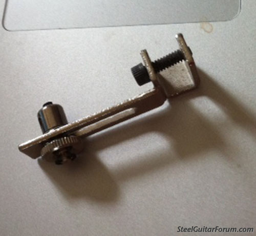
I was worried about that. What if you replaced the thumb wheel with a hex nut and used a small wrench? I found this picture which looks like it would work better. I may abandon this design altogether.Ross Shafer wrote:Hi Tim, I bought one of these many years ago...total joke. Getting one's fingers down into a loaded guitar to tighten this up while holding it in the desired height position was an exercise in frustration. Then getting it tight enough to hold was challenging without needle nose pliers.
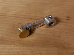

I made those cranks in the pic for my PP to better time the raise on 1 & 2. They work, but not super practical to adjust in place. Ross's Blanton-style cranks, similar to the Springfield cranks in your other pic, are a much better solution. The only real advantage to this sort of design IMO is that it's compact.Tim Toberer wrote:...What if you replaced the thumb wheel with a hex nut and used a small wrench? I found this picture which looks like it would work better. I may abandon this design altogether...


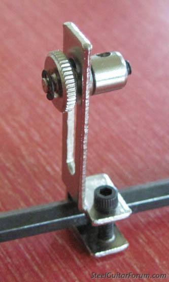
The clamp mechanism with the thumb nut is independent of the barrel that the pullrod connects to. That thumb nut clamp mechanism has a smaller diameter through hole, the barrel clamp for the rod has a corresponding axle extending off one side that feeds through that hole and is secured on the other end with the small C clip so it can rotate freely in the hole.Tim Toberer wrote:...I am still confused by the design of the Linkon, I can't figure out how the part that pivots on the end is attached...
Thanks for the added angles of your bell crank! I love the minimal design, and I think it would work with my current setup. Curious how you made it? It looks like you possibly attached the arm to a shaft collar with a machined shoulder? I think this style would be perfect, cause I don't plan on doing on the fly adjustments, just need a little flexibility to even out my lowers and raises. Once it's set it should be fine. I also plan on making my pivot arm adjustable to give me a little more flexibility, since I don't have the space for a tall bell crank. Blanton/Sierra style bell cranks are really a beautiful design, but seem pretty labor intensive. I am always looking for an easier way I suppose.Ian Worley wrote:I made those cranks in the pic for my PP to better time the raise on 1 & 2. They work, but not super practical to adjust in place. Ross's Blanton-style cranks, similar to the Springfield cranks in your other pic, are a much better solution. The only real advantage to this sort of design IMO is that it's compact.Tim Toberer wrote:...What if you replaced the thumb wheel with a hex nut and used a small wrench? I found this picture which looks like it would work better. I may abandon this design altogether...
Ok now I see! I was thinking it had to be something like this. Seems overly complicated.he clamp mechanism with the thumb nut is independent of the barrel that the pullrod connects to. That thumb nut clamp mechanism has a smaller diameter through hole, the barrel clamp for the rod has a corresponding axle extending off one side that feeds through that hole and is secured on the other end with the small C clip so it can rotate freely in the hole.

This is so true, and there are lots of little parts in a pedal steel guitar! I really appreciate the help!Ian Worley wrote:
The smaller the part, the more difficult it becomes to make something that functions precisely using manual tools. Perhaps there is something in here you can parlay into a more practical design. Keep us posted!
