Nashville 400 - Fails ESR Testing

Steel guitar amplifiers, effects, etc.

Moderator: Shoshanah Marohn

Post Reply
User avatar
Bob Lawrence
Posts: 1094
Joined: 6 Oct 2001 12:01 am
Location: Beaver Bank, Nova Scotia, Canada

Nashville 400 - Fails ESR Testing

Post by Bob Lawrence »

The most significant capacitor property is its capacitance. The second most important factor is the ESR (Equivalent Series Resistance) An ideal capacitor is a purely reactive component with a 90-degree phase angle between current and voltage. In the real world a capacitor needs to be modelled as an ideal capacitor in series with a resistor, representing the losses introduced by the component. A capacitor can be tested with a capaticance meter and measure it full rated value but still have a high ESR. The easiest way to test the ESR is with a ESR meter. Image

For example: High ESR can degrade a guitar signal if the capacitor is in the signal path. The testing is not an exact science because there are so many types and manufactures of capicitors but there are charts available and when in doubt compare the capacitor with others in the circuit (with the same value )or with a good spare you may have in your junk box.

There are many ESR testers on the market and the one I use is a PEAK Atlas ESR.

From the test Peak website:
Simplicity Measuring a capacitor's ESR (equivalent series resistance) is a great indicator of capacitor condition. The Atlas ESR offers instant results, just connect the probes and press test. You can even use the Atlas ESR in-circuit, saving you the trouble of removing capacitors. When testing capacitors out-of-circuit, the unit will also display the capacitance.All You Need Traditionally, ESR can be a tricky thing to measure, which is a shame, it's a very useful diagnostic parameter. Of course, ESR meters are available from various sources, some are very famous in the repair sector, but the Atlas ESR is more than just another ESR meter. For a start, it's smart, both in looks and in brain. It can measure and compensate for the effects of measuring in-circuit, it also knows that you don't want to be hassled with capacitor polarity.

URL: http://www.peakelec.co.uk/content/products/atlasesr.html

============================================

Nashville 400 Test Results.
=====================================
All tests below are out of circuit tests:

C1 - High/Low gain input.
Marked Value - 2uF @ 35 Volts
LCR Meter - Capacity test - 2.726 uF
ESR Meter- Measured Capacity - None
Typical ESR value expected - 3.2 ohms
ESR Measured - 10.0 ohms (same as the in circuit test)
ESR Test Result - failed
============================================

C8 - Effects loop
Marked Value - 2uF @ 35 Volts
LCR Meter Capacity test - 4.211 uF
ESR Meter Measured Capacity - Doesn't show
Typical ESR Value expected - 3.2 ohms
ESR Measured - 10.0 ohms (same as the in circuit test)
ESR Test Result - failed
============================================
Junk box capacitor test to compare it with C1 and C8
Marked Value - 2.2 uF @ 50V (closest one I had)
LCR Meter test - 2.920 uF
ESR Meter - measured value 2.834 uF
ESR Test - 00.85 ohms
============================================

C15 - EQ low
Marked Value - .047 @ 400Volts
LCR Meter - capacity test - 47.36 nF
ESR Meter - measured capacity - 35.94 nF
ESR Measured Value - 003.7 Ohms
ESR Test Results - Failed

When compared to another capacitor of the same value(C14):

C14
Marked Value - .047 @ 400Volts
LCR Meter - capacity Test - 47.36 nF
ESR Meter - measured capacity - 35.53
ESR Measured - 001.2 ohms
ESR Test Results - Passed

Junk Box selected capacitor
Marked Value - .047 @ 50V (closest I had)
ESR meter measured capacity - 37.14 nF
ESR measured value - 001.5 Ohms
ESR Test Results - Passed
============================================
Interesting facts:

C1, C8, and C15 were replaced as part of the Peavey, Tone Circuit Modification (kit) I completed around April 3 /1997

Food for thought:
- Could the parts have been bad from day one?
- Did the mod stress the parts in some way?
- Should I notice any difference when I change them?
- Should I replace the C1 and C8(electrolytic) with the same parts or use a different type (that's my plan) of capacitor such as a polypropylene Film type?

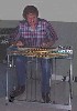
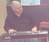
Picture of the tester in action:
Image

<font size="1" color="#8e236b"><p align="center">[This message was edited by Bob Lawrence on 19 July 2005 at 09:57 PM.]</p></FONT>
Wes Bakken
Posts: 17
Joined: 10 Feb 2004 1:01 am
Location: Sun City, AZ

Post by Wes Bakken »

Bob, I am not an expert on capacitors, but I usually replace all the electolytics in my Nashville 400 every 4 or 5 years. They can dry out and affect your sound. Every time I change them out, the amp sounds better. This may be similar to a car wash, that is, my car seems to run better after a wash and wax. Peavy probably would be a good source, or perhaps your local electronics store. Try "Digi-Key.com" or "JDR.com" or "Newark.com" Search for "Capacitors"
wes
User avatar
Jack Stoner
Posts: 22087
Joined: 3 Dec 1999 1:01 am
Location: Kansas City, MO

Post by Jack Stoner »

I wonder is the "in circuit" measurement is really accurate. I've always removed the component or at least lifted one end when I make a measurement so nothing else in the circuit will or can have an effect.

That was part of "basic troubleshooting 101" in electronics school.
User avatar
Dave Grafe
Posts: 4457
Joined: 29 Oct 2004 12:01 am
Location: Hudson River Valley NY
Contact:

Post by Dave Grafe »

Your poly caps are definitely a superior component to electrolytic ones both in terms of longevity and audio performance.
User avatar
Brad Sarno
Posts: 4916
Joined: 18 Dec 2000 1:01 am
Location: St. Louis, MO USA
Contact:

Post by Brad Sarno »

That's why I love to replace signal path electrolytic cap's with good polypropylene or polystyrene ones. The film caps also don't go bad over time like the electrolytics. When the value gets to be over 5uF, the film caps just get too physically large sometimes. That's when I try to replace the electrolytics with Black Gate brand electrolytics. They sound and perform better than the typical types. Panasonic has some good sounding electrolytics too. Black Gate may be out of business now.

Brad Sarno
User avatar
John Daugherty
Posts: 2188
Joined: 13 May 2004 12:01 am
Location: Rolla, Missouri, USA
Contact:

Post by John Daugherty »

I would not trust any "in-circuit" test. Take that cap out of circuit and you will get a valid reading.
Keith Hilton
Posts: 3730
Joined: 1 May 1999 12:01 am
Location: 248 Laurel Road Ozark, Missouri 65721
Contact:

Post by Keith Hilton »

Bob, there are places where a low ESR is good. Parts houses like Mouser and Digi Key list capacitors with low ESR.
User avatar
Ken Fox
Posts: 9620
Joined: 20 Apr 2001 12:01 am
Location: Nashville GA USA

Post by Ken Fox »

Excellent info! Also guys, note he did make the test "out of circuit". The ESR is the leading failure I see in filter caps. As the cap becomes more resistive it loads down the B+ power supply! Caps that test good on a standard tester can still be bad due to a high ESR. I often see the B+ improve 10 to 20 VDC in old Fender amps after a cap job! As the cap gets older it can go to a dead short. I have seen this in an old Twin reverb and a 1965 Deluxe I restored a few years back.
User avatar
Jack Stoner
Posts: 22087
Joined: 3 Dec 1999 1:01 am
Location: Kansas City, MO

Post by Jack Stoner »

Ken, look at the picture. The tester reads "In circuit" and it looks like the leads are connected to a component that's still connected on both ends.

Being an "old time" tech (I started out in tubes - before there were transistors) and out of circuit for any component testing was the "standard".
Michael Whitley
Posts: 50
Joined: 4 Feb 2005 1:01 am
Location: Oxford, Mississippi, USA

Post by Michael Whitley »

Thanks for the info, Bob. Caps seem to be the weak link in the chain. I know some guys parallel a lower-capacitance poly cap with an electrolytic - I'm assuming it's to address this issue.
User avatar
Bob Lawrence
Posts: 1094
Joined: 6 Oct 2001 12:01 am
Location: Beaver Bank, Nova Scotia, Canada

Post by Bob Lawrence »

Ken,

You are correct all of the measurements listed in the text above( and as indicated in the text above) are out of circuit tests. The picture of the tester is a in circuit test but was only used to show what the tester looked like and not a specific test. I checked all of the capacitors in-circuit (a few times each) and any that failed the test were taken out and re-tested at least twice. ESR is also tempature sensitive and I ensured that the ambient temperature did not exceed 20 degrees C(68'F)

Wes: I agree. It's just good maintenance to change them, (you don't have to measure them) although, I usually do it after about 10 years for any amp that I use on a regular basis.

Jack: Just for you I will post a few more pictures to show the same cap being tested out of circuit and being compared to another cap from my junk box. For the record, there was no difference testing any of the caps in or out of circuit. Also, one of the reasons that I purchased this model ESR meter was that it has the ability to test caps in or out of circuit. My main goal was to be able to test the capacitors (in circuit) for the IVL Steelrider (surface mount) preamps. It works great for that as well.

Brad: Thanks! I will check the Panasonic line at Digikey.

Keith: Are you indication that high ESR could be good for something? I have never heard of a case where that was so but if I am wrong please let me know where. (maybe it's not what you meant but that's how I interpreted your statement) To me High ESR has always (TV's, VCR's etc...) been a problem but it really got my attention when I started repairing computer switching power supplies.

Trivia:
Home page for the guy (Bob Parker - Australia) who designed the first ESR meter: http://members.ozemail.com.au/~bobpar/

==============
Cap - C8: Tested out of circuit

Image

A cap from my junk box to use for comparison(not quite the same rating but the closest I had)

Image
User avatar
Jack Stoner
Posts: 22087
Joined: 3 Dec 1999 1:01 am
Location: Kansas City, MO

Post by Jack Stoner »

OK, I see your measurements. But, will the in-circuit testing work for EVERY case? I don't do amp work for a living anymore, but if an in-circuit tester was not accurate 100% of the time, it's not a good tool for a working tech.
User avatar
Brad Sarno
Posts: 4916
Joined: 18 Dec 2000 1:01 am
Location: St. Louis, MO USA
Contact:

Post by Brad Sarno »

Those 2.2uF caps in the older Peaveys are the first things I replace along with the main filter caps. Digi-Key and Mouser sell some nice 2.2uF polypropylene film cap's that sound great. Those caps in the pic's are interstage coupling (DC blocking) caps and they carry the entire signal thru them. There are a small handful of them in the path. The sonic improvement is quite obvious. More detail, more silky sounding, smooth, clear highs. I have noticed that brand new caps sound a bit bright, but after a few dozen hours of being powered up and having voltage on them that the tone mellows and settles in. It's always tough to accurately judge the sound of a recap because the fresh parts just don't sound like they will eventually. Whenever I recap an old Session or something like that, I like to leave the amp on 24/7 for a couple of weeks. You can really hear that the tone has settled in after that. I believe the only reason that the stock caps are aluminum electrolytics is a cost issue. It's standard practice. It's not that the tone is bad with them, it's just that there is some loss of presence and detail, kind of a veiled or smeared sound compared to the good film types. I'm a bit obsessive with caps, but once you start to mess with them and notice the sonic differences, it's hard to go back. I recently replaced all the little yellow ceramic/monolithic signal caps in my NV112, and man oh man it really made a sweet amp noticeably sweeter. I will warn you, that's a VERY delicate board to work with so I don't necessarily recommend it as I would on a Session or NV400. Back to the topic, ESR is a pretty audible factor when there are enough electrolytic caps in the signal path.

Brad Sarno
Donny Hinson
Posts: 21192
Joined: 16 Feb 1999 1:01 am
Location: Glen Burnie, Md. U.S.A.

Post by Donny Hinson »

Hmmm..."ESR"? Is this related to the characteristic we used to refer to as "leakage"? One of my old "seat of the pants tests" for capacitors has always been to see if they heat up in a circuit. In the old days, I'd touch a capacitor with the back of one of my fingers. If it was warm (indicating leakage), I'd replace it. Nowadays, inexpensive digital IR thermometers can sense temperature changes as small as a tenth of a degree. It seems that, like leakage, a high ESR under operating conditions (with a signal applied) might cause the same sort of detectable heating in the component. More signal, more heating due to the resistance.

Your thoughts, gentlemen?
User avatar
Blake Hawkins
Posts: 1844
Joined: 4 Aug 1998 11:00 pm
Location: Florida

Post by Blake Hawkins »

Bob,
I have a Sencore "Z Meter II" which measures ESR.
Included with it is a chart for the maximum
permissable ESR based on the EIA specs.

In it the max for a 2.2 mfd, 25 volt, aluminum cap is 211 ohms.

Your spec is much lower.
Could it be that the lower specs are needed for switching regulators and computers,
while the older, higher readings are OK for radios,TV's and amplifiers?

Blake
Keith Hilton
Posts: 3730
Joined: 1 May 1999 12:01 am
Location: 248 Laurel Road Ozark, Missouri 65721
Contact:

Post by Keith Hilton »

Bob, I meant low ESR is good, high ESR is bad. In many cases I try to order low ESR capacitors and pay extra for them. Hope this information helps.
David Rich
Posts: 21
Joined: 30 Mar 2001 1:01 am
Location: Lexington, KY

Post by David Rich »

Sounds good. How much are they and where can I get one? Also, can anyone recommend a good in circuit transistor checker?

Mouser has some polyester film caps by Cornell Dubilier up to 10uf @100 or 250 VDC. Higher voltages available at smaller uf values.
User avatar
Will Holtz
Posts: 335
Joined: 5 Mar 2004 1:01 am
Location: San Francisco, California, USA
Contact:

Post by Will Holtz »

The in-circuit test mode probably assumes that the resistance between the test nodes is significantly smaller through the cap than the effective resistance that the cap sees from the remainder of the circuit. Thus the resistance of the cap dominates the measurement. Given that caps generally should have a resistance of less than an ohm or two, this assumption will be valid for most circuits. However, there are cases where this will not hold. Off the top of my head, I can think of some common radio circuit topologies that could mess up this measurement.
User avatar
Bob Lawrence
Posts: 1094
Joined: 6 Oct 2001 12:01 am
Location: Beaver Bank, Nova Scotia, Canada

Post by Bob Lawrence »

Donny: I agree that you can generate plenty heat with a high ESR cap but it depends on the circuit. C1 above does not generate any heat. If we are talking about riple current in a power supply and high ESR then sure. Last winter I had 11 caps go on my computer motherboard. Plenty of heat was generated before it quit.

Computer industry Story - Why all the low ESR caps quit:
http://www.burtonsys.com/bad_BP6/story3.html

Blake: Here's a note I took from one the the ESR meter's instructions:
"
(2) The "Approximate worst ESR values" table on the front of the meter were taken from a fairly old capacitor catalog, and capacitor technology has evolved a bit since then. Many 105 degree C electrolytics have an ESR up to nearly double those values even when brand new, and other electrolytics have a lower ESR even when old. From my experience if an electrolytic has an ESR more than double the table value for its capacitance and voltage rating, it's wise to check it against a new one and/or replace it to remove the chance of it causing problems in the future."

============================================
The ESR tester and cap chart that I use are the newest/latest-updates on the market.


Keith: Ok, your off the hook. Image

David R. The Peak company listed company also sells a semiconductor analyser. I've been using it for over a year and like it.

Will: The ESR tester - low value spec for
ESR Value/Resolution is as follows:

ESR Value: 0.00 (ohms) - 1.00 (ohms) - Resolution = 0.01 (ohms)
User avatar
Bob Lawrence
Posts: 1094
Joined: 6 Oct 2001 12:01 am
Location: Beaver Bank, Nova Scotia, Canada

Post by Bob Lawrence »

Theory question (1): Do you need a really need a capacitor for the input of modern op amps to block DC? The reason I ask is that with older transistor and bi-polar op amp designs you wanted to block the DC so that the input signal didn't upset the transistor bias but is it necessary with modern op amps. With all the modern design circuity such as low bias current op-amp inputs (FET) and all the protection built in to modern op amps is it possible to direct couple them? (just have a look at the internals of an op amp such as the OPA2004 for example) I had a look at my old Op amp cook book but it's so out of date it's no help. I will order the new Walter J Jung "Op Amp Applications book" to see what's new when time permits. Maybe I could put a jumper across the holes in the board for C1 etc...

Theory question (2): I hear plenty of references to that "solid-state sound" Could it be more to do with low grade capacitors (specifically low grade electrolytic's on op amp inputs). A question for for someone like Brad who has done plenty of Cap work in the past. Did you have ever have a situation when you referred to any guitar amp with such terms as ("solid-state sound") but felt that it wasn't a warranted label once you upgraded the caps in the audio path.

Theory question (3) Has anyone upgraded the total capacitance of the (power supply = 2 X 4700uf @ 55 Volts) electrolytic caps in the Nashville series of amps such as the Nashville 400. I did read somewhere in the past(from a tube amp book) that you could increase the bottom end (bass response) with additional capacitance.

Ok I'm all done and will go back to sleep now. Image

User avatar
Bob Lawrence
Posts: 1094
Joined: 6 Oct 2001 12:01 am
Location: Beaver Bank, Nova Scotia, Canada

Post by Bob Lawrence »

The new Walter J Jung Op Amp Applications book is on order from Amazon and should be here by Friday. Maybe it will have a few answers.
Post Reply