| Author |
Topic: Individual Tube Bias Mod for Traynor YRM-1 Reverb Master |
John Limbach
From:
Billings, Montana, USA
|
 Posted 20 Jun 2015 8:31 am
 |
|
Picked up a YRM-1 head recently for a good price. Someone had replaced (badly) many of the electrolytic caps with some wildly increased values. Once I straightened that out, it sounded better.
This is a fixed bias circuit so I checked the plate dissipations using a Compu-Bias device. Pricey but really simple and tells you everything that's going on without any calculations.
At any rate, it indicated that one of the tubes was running at 25 watts and the other at around 14. Since the maximum plate dissipation of the EL34s is 25 watts, this was not good. Obviously the tubes are wildly mismatched.
So, I added a simple variable bias mod to the power supply. The first one I put in varied the bias to both tubes together. This wasn't satisfactory because when I increased the bias voltage enough to bring the hot tube down to about 75% plate dissipation, the other was running really cold, say about 40%. What to do? Other than getting a new balanced set of tubes, of course.
I decided to see if I could easily change the mod to bias the tubes individually. Long story short, yes you can and it works nicely.
After finishing the mod I am now able to set the bias on either tube to yield a plate dissipation anywhere in the range of 30-100+%. I've set it for now at 65% on both tubes and it sounds great.
Here's the original schematic of the YRM-1:
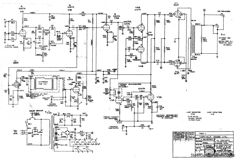
Here's a closeup of the power supply section of the schematic in the stock configuration:
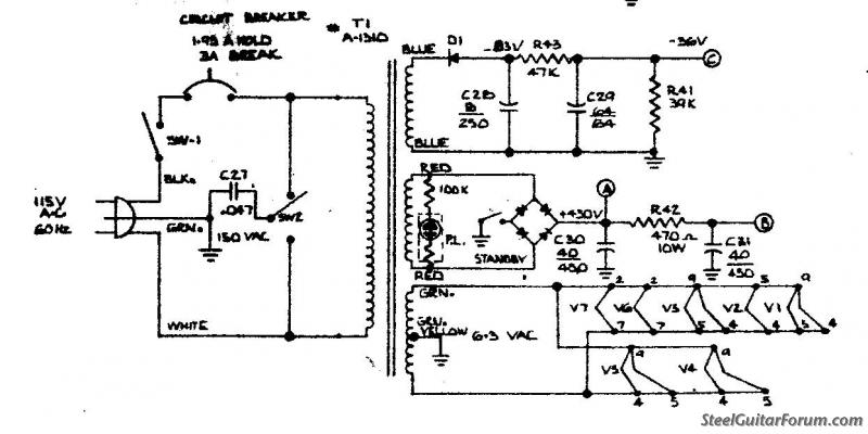
In the mod, I added two 25K linear taper pots with recessed screwdriver adjustment. Since I don't use the footswitchs, I took out the jacks for Reverb and Tremelo and mounted the pots in the existing holes in the panel. I wanted to be able to readjust things when replacing tubes without having to take the top off, but you certainly could use trimpots and mount them on the eyelet board if you want.
Here's the schematic of the modified bias supply. The original configuration produced about -36VDC but I needed more than that to control the tubes, so I replaced R41 (39K) with a 50K resistor. This gave me -46VDC which worked fine.

Works well and is very stable. I suspect this would work with most similar amps with some tinkering of values. |
|
|
|
Mike Wheeler
From:
Delaware, Ohio, USA
|
Posted 20 Jun 2015 11:43 am
|
|
Very nice explanation of your mod, John. Thanks much.
_________________
Best regards,
Mike |
|
|
|
Bill Sinclair
From:
Waynesboro, PA, USA
|
Posted 21 Jun 2015 4:49 am
|
|
| Yes, thanks! May have to give it a try. That compu-bias is a pretty neat toy. Since I only bias one or two amps a year, I can't justify it. I was thinking about buying a couple of those sockets that have the built in 1 ohm cathode resistor so I don't have to pull the chassis just to bias the tubes. Any experience with those? I don't remember who makes them but seems like I've seen them on ebay. |
|
|
|
John Limbach
From:
Billings, Montana, USA
|
Posted 21 Jun 2015 6:25 am
|
|
| I think the Weber Bias Rite will work. They sell the socket adapters individually I think, as well as in sets with the meter, etc. |
|
|
|