| Author |
Topic: Clean volume from tube amp |
David Higginbotham
From:
Lake Charles, Louisiana, USA
|
 Posted 24 Oct 2011 10:41 am
 |
|
I have a Carvin X-60 with EH 6L6 tubes and have managed to get a really good tone out of the amp. My problem is lack of clean volume before it starts to distort. I've tried replacing the V-1 preamp 12AX7 to a 12AT7 with some improvement and now to a 12AY7 with a slight improvement. I'm not certain I can get where I want to be with this but would like suggestions to get the maximum amount of clean volume from the amp.
Thanks,
Dave
_________________
'92 GFI D-10 8&6, ‘67 Emmons Bolt-On D-10 8&7, Walker preamp, Sarno Tonic preamp, Tubefex, Stewart power amps, Carvin XT tube amp, Webb Cabinets, all vintage JBL’s! |
|
|
|
Paul Sutherland
From:
Placerville, California
|
Posted 24 Oct 2011 1:37 pm
|
|
Isn't this amp supposed to have EL 34 power tubes; not 6L6s? In any event, the literature I see on the web indicates there are only two power tubes. It's not surprising to me that you can't get clean higher volumes, as those two tubes, whatever they are, are simply working too hard.
Is the amp clean at low volume?
PS: I am definitely not an expert in these matters. |
|
|
|
David Higginbotham
From:
Lake Charles, Louisiana, USA
|
Posted 24 Oct 2011 1:58 pm
|
|
Paul, thanks for your input. The X-amps were issued with both EL-34's and 6L6 power tubes. I've had both models in the 100 watt version and could get enough clean volume to make your ears bleed. This is a really good sounding amp just not the clean volume I expect the amp should have.
Dave |
|
|
|
Dave Hopping
From:
Aurora, Colorado
|
Posted 24 Oct 2011 2:00 pm
|
|
A quick check around the 'Net shows the X-60 is rated @ 60W RMS.Like a number of other tube amps it sounds pretty good at bedroom and(sometimes)studio volume.Stage volume is something else again,and to keep things clean there,you'll have to add another amp,or mic the X-60,or both.
Steel guitar hits an amp at least as hard as electric bass does and while those mid-power guitar amps do fine onstage with a six-string,they run out of headroom fast if presented with a heavier load. |
|
|
|
David Higginbotham
From:
Lake Charles, Louisiana, USA
|
Posted 24 Oct 2011 4:31 pm
|
|
Dave thanks for the input. I've used a 40 watt hot rod deluxe and a 60 watt deville with plenty of volume. I had to change preamp tubes in the deville and mod the reverb and bass/mid controls on the HR deluxe but got plenty of volume from both.
I was wondering how this mod would affect the rhythm channel???
http://trujeque.com/x_mod.html |
|
|
|
Rich Gibson
From:
Pittsburgh Pa.
|
Posted 24 Oct 2011 6:03 pm
|
|
Hi David. I think you can get the sound you like, with more headroom, using a more efficient speaker.
D or K series JBL's,Black widows,Weber Cali or some of the new Neo speakers work well.I use a 50 watt 2 6L6 tube amp with a Jensen Neo 15.It gets as loud as I care to play.The speakers in most guitar amps are designed to break up earlier than we want for steel and the steel hits them harder as well.
There are varying opinions on this subject and a forum search will turn up several informative threads.
hope that helps. |
|
|
|
David Higginbotham
From:
Lake Charles, Louisiana, USA
|
Posted 24 Oct 2011 6:53 pm
|
|
Thanks Rich! I should have mentioned I'm currently running into a 15 inch cabinet loaded with an Evans Eclipse 4 ohm. I have a 12 inch Blue Marvel on the way but using steel friendly speakers. I'm using Emmons s/c pickups & a Hilton or Goodrich L10K.
Dave |
|
|
|
Steve Lipsey
From:
Portland, Oregon, USA
|
Posted 24 Oct 2011 8:53 pm
|
|
Check out brad Sarno's suggestion in my thread on adding a lower level input to my relatively high-gani amp.....added clean headroom...I added a switch on the back panel to disconnect the 25mfd cap on the input tube grid, as Brad suggested...as he says, it makes it "more steel friendly"
http://bb.steelguitarforum.com/viewtopic.php?t=213319&highlight= |
|
|
|
David Higginbotham
From:
Lake Charles, Louisiana, USA
|
Posted 25 Oct 2011 5:51 am
|
|
Steve thanks for the link! I obviously missed that post as I try to catch everything that Brad gives advice on. It may be the solution I'm looking for.
Dave |
|
|
|
David Higginbotham
From:
Lake Charles, Louisiana, USA
|
Posted 27 Oct 2011 4:55 am
|
|
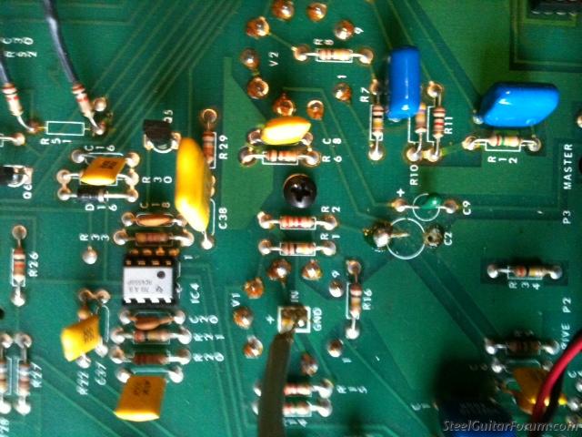
I think I found the problem of lack of clean volume from the clean channel. Someone added this resistor in the board likely to add more drive. Hopefully I can remove the resistor and get the amp back as it should be.

Last edited by David Higginbotham on 27 Oct 2011 5:10 am; edited 1 time in total |
|
|
|
Jay Ganz
From:
Out Behind The Barn
|
Posted 27 Oct 2011 5:06 am
|
|
That's a capacitor and a resistor. Looks like they put it in parallel with the C2 capacitor that's on the top side of the board. 
Last edited by Jay Ganz on 27 Oct 2011 5:09 am; edited 1 time in total |
|
|
|
David Higginbotham
From:
Lake Charles, Louisiana, USA
|
Posted 27 Oct 2011 5:08 am
|
|
| Jay, look at one end of the capacitor and you will see the addition on C-2... |
|
|
|
Jay Ganz
From:
Out Behind The Barn
|
Posted 27 Oct 2011 5:11 am
|
|
| Oh yeah....looks like 2 resistors (total) and the one cap were added, right? Is the original C2 still in there on the topside? |
|
|
|
David Higginbotham
From:
Lake Charles, Louisiana, USA
|
Posted 27 Oct 2011 6:09 am
|
|
Jay, the pic is a bit misleading as only one resistor is attached to the capacitor going into C-2. I removed both last night with less than stellar results. I was trying not to remove the board from the chassis. But since I'm unable to get a good solder in place, it will be a necessity now. I'm no amp guru by any stretch and not really sure what the purpose of this capacitor is or if it is the correct value that should be in place. I can only determine that it was altered. I found the schematics for X-amps here and will try my best to get the amp back up to par. It really sounds great when it works correctly...
http://www.carvinmuseum.com/pdf/amps/xamp-revk.pdf
http://www.carvinmuseum.com/pdf/amps/x100b-22-k-carvinschematic.pdf |
|
|
|
Steve Lipsey
From:
Portland, Oregon, USA
|
Posted 27 Oct 2011 9:32 am
|
|
Looks like the cap should be a 22mfd (although one schematic says 22 and the other says .22), and the resistor shouldn't be there - your picture didn't include enough but it looks like there may be a "R2" above the cap, it is probably still on the board. It changed somewhat from version to version of this amp (can you tell which your is? does it say on the board?).
So maybe the cap should be in the circle that says C2, attached to the solder points on either side, and the resistor should be gone.
But I can't really tell if I can see clearly what is going on, so check for yourself.....

 |
|
|
|
David Higginbotham
From:
Lake Charles, Louisiana, USA
|
Posted 27 Oct 2011 11:43 am
|
|
Stephen, first let me thank you for your help! I've done minimal work on tube amps and certainly welcome any assitance offered by someone with more knowledge in this area than I possess!
Here is a larger pic of the board. I knew the resistor didn't belong in there and will try to replace the capacitor with the same value if I can find one. But this capacitor is 10UF/50V. Not sure how critical that is? Any advice is greatly appreciated!
 |
|
|
|
Steve Lipsey
From:
Portland, Oregon, USA
|
|
|
|
Steve Lipsey
From:
Portland, Oregon, USA
|
|
|
|
Larry Robinson
From:
Peachtree City, Georgia, USA
|
Posted 27 Oct 2011 2:04 pm
|
|
| The resistor is there to provide bias for the tube(called cathode self bias). The cap (cathode bypass cap) keeps the voltage constant across the resistor. if you remove the cap, degeneration is introduced which lowers the tube gain and improve fidelity. if you remove the resistor, then there is no bias for the tube. The voltage drop across the resistor puts the cathode voltage positive with respect to the control grid. This is the bias voltage for the tube. 22 mfd sound correct for cap. Hope the helps. |
|
|
|
David Higginbotham
From:
Lake Charles, Louisiana, USA
|
Posted 27 Oct 2011 2:49 pm
|
|
Thanks Larry! I wish I could say that clears everything up for me, but I'm a bit confused as to what will happen with the cap removed completely and what will happen if I replace the cap with the value showing in the schematics? I will leave out the additional resistor that was attached of course hoping to get as much clean volume as possible from the amp. But the cap I removed was 10uf and wondering what affect this had compared to the correct one.
Again, thanks for you help!
Dave |
|
|
|
Mike Wheeler
From:
Delaware, Ohio, USA
|
Posted 27 Oct 2011 5:12 pm
|
|
David, if you look at the schematic snippets that Steve posted, you'll see the 22mfd cap. Someone has replaced that cap with the 10mfd, non-polarized, cap and a series resistor that is in your amp now. Maybe someone's attempt at a tone mod??
All you need to do is remove that cap/resistor combo, and install a 22mfd cap there instead.
In that circuit you don't need a non-polarized cap. (that's what the NP on the old cap means) A standard electrolytic will do fine. Make sure the negative side of the cap is soldered to the pad that the resistor was in...that's ground. Without seeing the schematic, I'd say a 50volt value would be fine.
_________________
Best regards,
Mike |
|
|
|
David Higginbotham
From:
Lake Charles, Louisiana, USA
|
Posted 27 Oct 2011 5:27 pm
|
|
Thank you Mike! That's something that even an "intellectually challenged Cajun" like myself can understand...
Guys, I really appreciate all of the info and assistance you've provided...Yes, the forum is a great place!
Dave |
|
|
|
Larry Robinson
From:
Peachtree City, Georgia, USA
|
Posted 28 Oct 2011 3:06 am
|
|
| David, the value of the cap should be 22 mfd, not 0.22. It's sole purpose is to keep the bias voltage constant. |
|
|
|
Steve Lipsey
From:
Portland, Oregon, USA
|
Posted 28 Oct 2011 5:27 pm
|
|
From Dave by email:
Looking at Brad's modification, he mentions snipping the capacitor on the first input tube. I'm unable to determine where that is located??? I still do not have the desired clean signal I desire. I did manage to change the other cap to the value indicated on the schematics tho.
and my reply:
Well, I actually looked at the whole schematic.....and it looks like that R2/C2 circuit is in the lead drive channel....the rhythm channel is the other half of that tube and has no capacitor there at all....
And that is the cap that Brad is talking about, so clipping it should cut the drive level, but only in the lead gain channel. Won't buy you more clean headroom in the clean channel.
Of course, there is one more idea, also suggested in my thread.....replace the V1 tube with a lower-gain tube., a pretty common mod.V1 is a 12AX7, according to the table in the bottom left of the schematic. Replace with a 12AT7 or 12AY7 (I forget which is lowest, Google would know). That would lower the gain on both preamp channels, which would increase headroom.
I'm not really an expert here, only have general knowledge, so I guess it is time to look for a more knowledgable source...I don't know what else further to suggest here....but a simple tube swap might do it. |
|
|
|
Jay Ganz
From:
Out Behind The Barn
|
Posted 28 Oct 2011 5:42 pm
|
|
| Steve Lipsey wrote: |
| Of course, there is one more idea, also suggested in my thread.....replace the V1 tube with a lower-gain tube., a pretty common mod.V1 is a 12AX7, according to the table in the bottom left of the schematic. Replace with a 12AT7 or 12AY7 |
I think he said he tried that already. |
|
|
|