Page 4 of 9
Posted: 29 Aug 2010 12:20 pm
by richard burton
I must confess, I'm a little bit annoyed at Mickey Adams laughing at my post, I thought I was making a valid point.
I thought he was better than that
Posted: 29 Aug 2010 12:28 pm
by Chris Lang
Richard say:
I must confess, I'm a little bit annoyed at Mickey Adams laughing at my post, I thought I was making a valid point.
I thought he was better than that
Don't worry, it was probably a nervous laugh. He meant no harm.
Posted: 29 Aug 2010 12:38 pm
by Bill Dobkins
I think you get better tone with a bent rod.
Posted: 29 Aug 2010 1:14 pm
by Earnest Bovine
Chris Lang wrote:No, still no good, and wouldn't be on the same plane. You still would have that nagging rise and fall at the "bent" part of the crossrod.
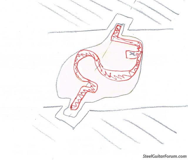
Chris, don't let this "nag" at you. The shape of the shaft makes no difference. Here are some illustrations to make clearer how I tried to show that a couple of hours ago.
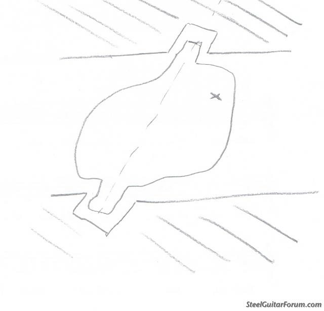
First, imagine that instead of a cross shaft, you have a brick or blob of rigid material. The pull rod is attached at the point marked X. If you rotate the brick, say 10 degrees, the point X moves, say 1 cm, toward you and your B string goes up to C#.
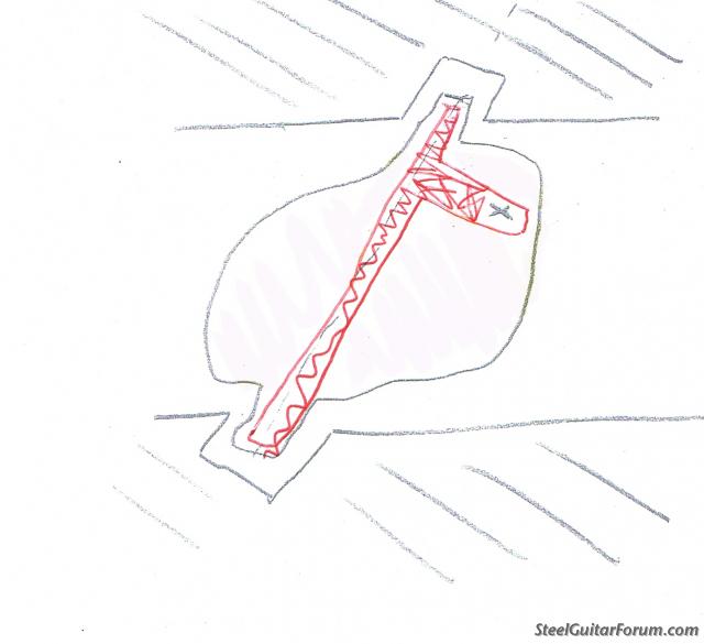
Now imagine that we cut away the pink part and leave the red part. If you make the same 10 degree rotation as you did before, the point X will move the same 1 cm as it did before, because the material is rigid. This could be brick material, or it could be a metal shaft with a rod puller attached like the cranks we all have on our guitars.
Next, suppose that instead of cutting away what we cut before, we cut away something else, for example:
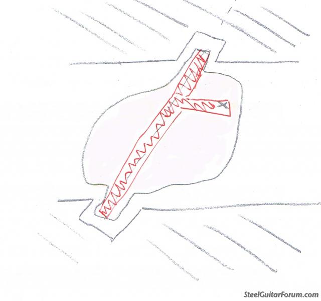
Again, the same 10 degree rotation will move the point X by the same 1 cm. The point X does not know what we cut away, as long as the material is rigid. The guitar will work exactly the same.
Next, suppose we cut away this part instead:
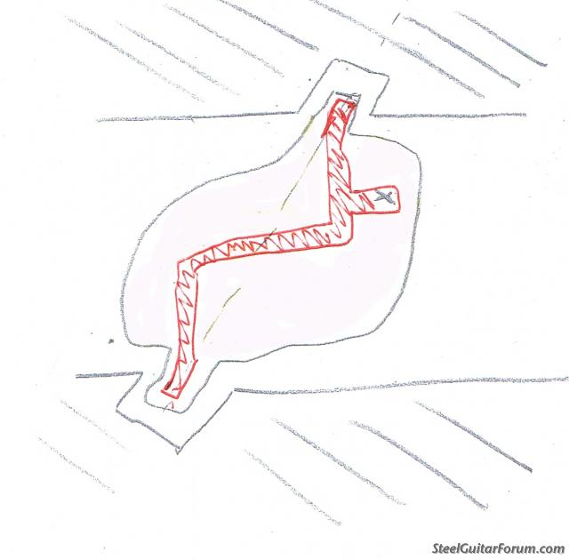
Obviously this could be a bent shaft with rod puller attached. The point X will move exactly as it did with the straight shaft. The point X (your pull rod) does not know what part you cut away.
We could even do this and it would make no difference.
Posted: 29 Aug 2010 1:30 pm
by Herb Steiner
'Fess up, Doug... you got that drawing from a urology textbook!

Posted: 29 Aug 2010 1:44 pm
by Stu Schulman
Posted: 29 Aug 2010 2:09 pm
by Greg Cutshaw
How about somebody put this design in Pro Engineer or even Google SketchUp and document the path followeed by the rod puller at the point where the pull rod attaches for both the "straight cross shaft" and the "Mullen design" as the cross rod is rotated? This results would be hard to argue with!
You would have to do this for rod pullers right next to the guitar apron versus rod pullers near the middle between the front and back aprons as these would yield different results for the Mullen design.
Greg
Posted: 29 Aug 2010 2:14 pm
by Chris Lang
Earnest,
I appreciate your illustrations, however, they do not show what Mullen has done.
The whole point of this is the fact that both ends of the crossrod must be on the same plane, in other words, the same
axis. For instance, the inside body aprons and steel reinforcements of all pedal steels are parallel. The crossrods extend from one side at 90 degrees to the other side of the apron at 90 degrees,
on the same plane.
If Mullen had used a straight crossrod, the bellcranks would still be pulling downhill, and to the side, since there is a difference in height between the two endpoints(axis).............
No, I'm sorry, but the "bent" crossrods are a design flaw........

Look at Mullen website. You will see what we are talking about.

Posted: 29 Aug 2010 2:16 pm
by Mickey Adams
Lmao
Posted: 29 Aug 2010 2:19 pm
by Michael Robertson
Bridge anyone?
Posted: 29 Aug 2010 2:21 pm
by Chris Lang
Greg says:
How about somebody put this design in Pro Engineer or even Google SketchUp and document the path followeed by the rod puller at the point where the pull rod attaches for both the "straight cross shaft" and the "Mullen design" as the cross rod is rotated? This results would be hard to argue with!
You would have to do this for rod pullers right next to the guitar apron versus rod pullers near the middle between the front and back aprons as these would yield different results for the Mullen design.
Greg
Great idea, Greg! I wish I had Pro Engineer.
You should do it for us!

Posted: 29 Aug 2010 2:22 pm
by Bill Lowe
How about that tone?????

Posted: 29 Aug 2010 2:54 pm
by Jimmy Lewis
I sat down at my steel just a few minyutes ago and you should have herd the physics coming ffom that thing just BEAUTIFUL.
Posted: 29 Aug 2010 2:58 pm
by Pete Burak
I can't find a link outside of this Forum showing a guy named Chris Lang who plays Pedal Steel.
Anyone here know Chris???
'Just Curious,
pete b.
Posted: 29 Aug 2010 3:05 pm
by Chris Lang
Greg says:
You would have to do this for rod pullers right next to the guitar apron versus rod pullers near the middle between the front and back aprons as these would yield different results for the Mullen design.
Excellent point!
But not for the guitar with the straight crossrod.
Folks, why is this?
Because the bellcranks on the G2 closest to the center of the rod (bend) will
rise and fall more than those closer to the ends.
I cannot see how anyone can even seriously question this................

Posted: 29 Aug 2010 3:09 pm
by Chris Lang
Pete:
I can't find a link outside of this Forum showing a guy named Chris Lang who plays Pedal Steel.
Anyone here know Chris???
'Just Curious,
pete b.
cell: 503-621-8209
Hey Pete, I'm right here! You can find me at
www.steelguitarforum.com !
I'm currently on the Mullen bent crossrods thread.
Give me a shout!
We'll hash out the details of the "bent" rods on the G2 !

Posted: 29 Aug 2010 3:16 pm
by Richard Damron
b0b -
Sorry, Cap'n, but you're wrong. With a bent shaft, e.g., Mullen's, there is no common axis. Given any displacement, the axis of one would, in space, be offset from the other by the degree of displacement. By way of illustration: - Mount two bearings between two support members such that there is a common axis between them, i.e., an imaginary straight line connects the axies of the bearings. Now, displace one of the bearings by any amount. Its' axis is now removed from its' original position by the measure of the displacement. They are no longer common.
In viewing the photos on the Mullen site, it is clear that the cross-shafts are mounted between two vertical plates and that the bearing centers are displaced - not on the same axis.
Chris Lang made that point quite clearly in his post above.
Earnest Bovine makes the salient point that the bearings were at two different heights re my statement above.
Chris and Earnest have both agreed with my assessment. The only unknown is whether Del Mullen has actually bent the bearing portions of the axle and/or allowed for the angular displacement of the axles in the bearings. I'm not accusing Mr. Mullen of being "cheap", by any means, since he makes a very fine instrument known to all but, I sincerely do not believe that he would go through all of the ultra-precision machining/mounting techniques so as to compensate for this error. I rather think that he chose to simply bend the shafts and accept the fact that there would be a small nonlinearity from end to end.
I must repeat that which I stated in my first post - I am NOT knocking the success of his design but, rather, attempting to aprise the membership of the mechanical error inherent in such a simple effort.
Like a broken record, I repeat myself: It WORKS so I'm not panning it whatsoever.
I hope that some of us have enlightened the rest as to the mechanical inconsistency contained therein.
Respectfully,
Richard
Posted: 29 Aug 2010 3:22 pm
by Chris Lang
Richard says:
b0b -
Sorry, Cap'n, but you're wrong. With a bent shaft, e.g., Mullen's, there is no common axis. Given any displacement, the axis of one would, in space, be offset from the other by the degree of displacement. By way of illustration: - Mount two bearings between two support members such that there is a common axis between them, i.e., an imaginary straight line connects the axies of the bearings. Now, displace one of the bearings by any amount. Its' axis is now removed from its' original position by the measure of the displacement. They are no longer common.
In viewing the photos on the Mullen site, it is clear that the cross-shafts are mounted between two vertical plates and that the bearing centers are displaced - not on the same axis.
Chris Lang made that point quite clearly in his post above.
Earnest Bovine makes the salient point that the bearings were at two different heights re my statement above.
Chris and Earnest have both agreed with my assessment. The only unknown is whether Del Mullen has actually bent the bearing portions of the axle and/or allowed for the angular displacement of the axles in the bearings. I'm not accusing Mr. Mullen of being "cheap", by any means, since he makes a very fine instrument known to all but, I sincerely do not believe that he would go through all of the ultra-precision machining/mounting techniques so as to compensate for this error. I rather think that he chose to simply bend the shafts and accept the fact that there would be a small nonlinearity from end to end.
I must repeat that which I stated in my first post - I am NOT knocking the success of his design but, rather, attempting to aprise the membership of the mechanical error inherent in such a simple effort.
Like a broken record, I repeat myself: It WORKS so I'm not panning it whatsoever.
I hope that some of us have enlightened the rest as to the mechanical inconsistency contained therein.
Respectfully,
Richard
I could not have explained it any better.
Very good post Richard...............
Posted: 29 Aug 2010 4:33 pm
by Bent Romnes
Richard Damron wrote:
"The only unknown is whether Del Mullen has actually bent the bearing portions of the axle and/or allowed for the angular displacement of the axles in the bearings.
Richard, there is no need to bend the bearing portions of the axle, as there is no angular displacement.
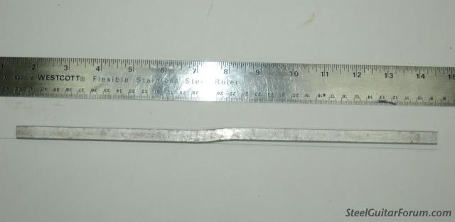
first, you bend the first part of the "S" then, you re-clamp and bend the other part back to end up on the same line. I just tried on a length of 3/8" square aluminum rod.
Notice the line I drew and how the left end of the shaft follows the line. The right end is off the line by about 3/16" due to the bending and except for my slight inaccuracy in the bending process, it follows the same line and is accurate enough to show that the bearing ends of the shaft is in fact not angularly displaced.
[/img]
Posted: 29 Aug 2010 5:14 pm
by Chris Lang
Bent bends again:
"The only unknown is whether Del Mullen has actually bent the bearing portions of the axle and/or allowed for the angular displacement of the axles in the bearings.
Richard, there is no need to bend the bearing portions of the axle, as there is no angular displacement.
first, you bend the first part of the "S" then, you re-clamp and bend the other part back to end up on the same line. I just tried on a length of 3/8" square aluminum rod.
Notice the line I drew and how the left end of the shaft follows the line. The right end is off the line by about 3/16" due to the bending and except for my slight inaccuracy in the bending process, it follows the same line and is accurate enough to show that the bearing ends of the shaft is in fact not angularly displaced.
Excellent bend, Bent!
You have unknowingly proved our point!
The right end is off the line by about 3/16" due to the bending and except for my slight inaccuracy in the bending process, it follows the same line and is accurate enough to show that the bearing ends of the shaft is in fact not angularly displaced.
the bearing ends of the shaft is in fact not angularly displaced
Huh?

Of course it is angularly displaced.
You just showed us with your own photo!

Two different axis!
 NOW
NOW
Imagine two parallel lines on each end of your "bend", both at 90 degree angles to the rod.
Now imagine the bend with two bellcranks mounted just within a couple of inches or so, on both sides of the bend. Now "see" it rotate.
You can envision the bellcranks rising and falling with the rotation. Also, there will be a slight tilting noticed at the top of each bellcrank.
Good job!

Posted: 29 Aug 2010 5:42 pm
by Ross Shafer
for anyone who's interested I modeled this up in Solidworks. Mating the bent rod at each end to the two different bores
concentrically will not allow the bent rod to rotate. The only way it can rotate is for some misalignment of the two rod ends within their respective bores to take place.
I'm not saying that anything is good or bad. I'm just offering up a computer simulation.
You can easily see the heart of the conundrum this design poses by checking out the animation I made. Email me and I'll send you a copy, but to view it you'll need to load a Solidworks EDrawings Viewer...it's free and can be found here
http://www.edrawingsviewer.com/
Once you've opened the file, over at the left you see a little icon that looks like a bit of film (should be the 7th one down), Hit that and the animation player will come up hit play and voila!
Posted: 29 Aug 2010 5:44 pm
by Bent Romnes
Chris,we were talking about the shaft ends. They are not angularly displaced to the holes they are mounted in
Posted: 29 Aug 2010 5:45 pm
by Jonathan Cullifer
It's a steel guitar, not a jet engine...and I like analogies, so here is one.
I have gotten the same sort of flak writing computer software. I don't have a degree in computer science, and I get scoffed at by those that do. Is my approach unorthodox? Yes. Does it work? Yes.
Personally, the bent rods are not something that I would probably do. At the same time, I have played several G2s and have no doubts about the performance.
As far as the lack of "physical correctness," ask yourself, "Does this idea solve the problem that it's trying to solve? Are there any side-effects that would keep it from doing so?" The theoretically impossible kills too many ideas before they get off the ground...
"In theory, there is no difference between theory and practice. But, in practice, there is."
Posted: 29 Aug 2010 5:50 pm
by Chris Lang
Bent:
Chris,we were talking about the bearing ends. They are not angularly displaced to the holes they are mounted in
Thats true, both ends of the rod go into the side apron at 90 degree angles.
HOWEVER!
They are each on
different axis, which is where the flaw comes into play.
They either have to have swivel bearings, or be allow enough tolerance to squirm in the recieving ends.
A physical design flaw either way.

Posted: 29 Aug 2010 6:01 pm
by Bent Romnes
So, you acknowledge that the shaft ends are not angularly displaced...this is what you tried to say when you said I had proved your point. All that writing for nothing, Chris.
Now follow me:
sure the axis is different... by a quarter inch. But that is ok and also sound engineering, because it is not like you say that the ends have to "squirm" as you scientifically put it. Instead it is like Mike said: That this is built to tolerances of .002 inches. That is a very good, sound tolerance and certainly no "squirming"
Chris it is not a design flaw if it works as intended, and that it does. It is just a flaw in the eye of the beholder who can't stand to see something new and innovative. I refer again to the old lady and the train


 [/img]