Correct wiring for power strip?
Moderator: Shoshanah Marohn
-
Jack Goodson
- Posts: 4773
- Joined: 21 Mar 2005 1:01 am
- Location: new brockton,alabama (deceased)
Correct wiring for power strip?
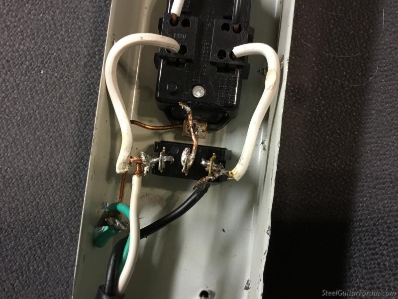
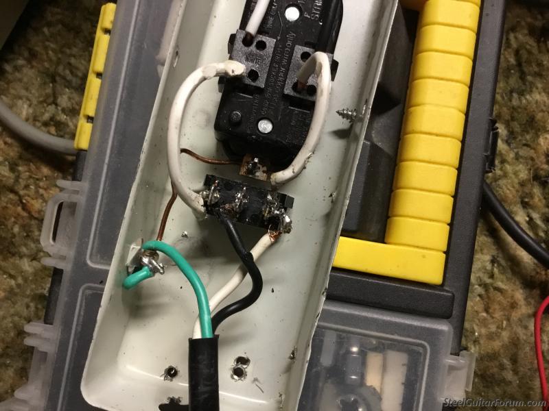
Here it is....anyone know what is wrong? You can test it with a meter and it is showing 121volts with the switch in the off or on position? Any help will really appreciated....thanks jack
-
Mike Wheeler
- Posts: 3058
- Joined: 18 Oct 2004 12:01 am
- Location: Delaware, Ohio, USA
-
Tim Russell
- Posts: 958
- Joined: 12 Apr 2015 7:45 am
- Location: Pennsylvania, USA
-
Jack Goodson
- Posts: 4773
- Joined: 21 Mar 2005 1:01 am
- Location: new brockton,alabama (deceased)
Switch?
Strange thing is this is how it was hooked up when I bought the seat that it goe,s in. It was not working at all when I got it so I replaced the switch and it works, I used it for a couple of hours last Saturday night before I realized that the switch was not cutting the power off. The ground wire was hooked up in the middle but I took it loose and it still works but still doe,s not cut off. I have replaced the on/off switch the 2/nd time....thanks jack
-
Jack Goodson
- Posts: 4773
- Joined: 21 Mar 2005 1:01 am
- Location: new brockton,alabama (deceased)
Diagram?
Anyone know where I could find a wiring diagram?....thanks jack
-
Bill L. Wilson

- Posts: 935
- Joined: 14 Aug 2012 12:31 pm
- Location: Oklahoma, USA
The Switch.
The switch is supposed to be a a cutoff for the black (hot) side of the circuit. The neutral (white) wire goes directly to the wide blade of the plug. There shouldn't be a ground wire connected to the switch. There should be a ground connecting the plug to the case and the plug receptical.......So, connect the black wire to one side of the switch, from the switch to the small blade side of the receptical....Connect the white wire directly to the large blade side of the receptical plug.....Connect the ground (green) wire to the case and the ground lug on the receptical. And pull all of that solder and wires apart and start over.
-
Dennis Detweiler
- Posts: 3488
- Joined: 8 Dec 1998 1:01 am
- Location: Solon, Iowa, US
It's definitely wired wrong. I think it's the wrong switch and should only have two terminals, but it can be done using one side of the switch (center terminal and left OR right terminal).
The black wire from the cord should go to one switch post. Another black wire from the other switch post should go to one side of the plug.
The white wire from the cord should connect directly to the other side of the plug.
Also, best to have someone make the connections that knows about the polarity and has basic wiring knowledge.
1976 Birdseye U-12 MSA with Telonics 427 pickup, 1975 Birdseye U-12 MSA with Telonics X-12 pickup, Boss 59 Fender pedal for preamp, NDR-5 Atlantic Delay & Reverb, two Quilter 201 amps, 2- 12" Eminence EPS-12C speakers, ShoBud Pedal, 1949 Epiphone D-8. Revelation preamp into a Crown XLS 1002 power amp.
-
Dennis Detweiler
- Posts: 3488
- Joined: 8 Dec 1998 1:01 am
- Location: Solon, Iowa, US
Bill covered it. Switch looks like an on to on (center post remains incoming hot?)If so, adds to the confusion.
1976 Birdseye U-12 MSA with Telonics 427 pickup, 1975 Birdseye U-12 MSA with Telonics X-12 pickup, Boss 59 Fender pedal for preamp, NDR-5 Atlantic Delay & Reverb, two Quilter 201 amps, 2- 12" Eminence EPS-12C speakers, ShoBud Pedal, 1949 Epiphone D-8. Revelation preamp into a Crown XLS 1002 power amp.
-
Jack Goodson
- Posts: 4773
- Joined: 21 Mar 2005 1:01 am
- Location: new brockton,alabama (deceased)
Switch?
This is just like the switch that came with the seat when I bought it from a forum member, and was hooked up the same way you see it now. The ground looks like it is connected to the switch but it is not....thanks jack.... an actual diagram would help

-
Bill A. Moore
- Posts: 1310
- Joined: 2 Jul 2007 3:17 pm
- Location: Silver City, New Mexico, USA
-
Jack Goodson
- Posts: 4773
- Joined: 21 Mar 2005 1:01 am
- Location: new brockton,alabama (deceased)
Switch?
Bill, I think I understand what you are saying, but would it be possible to send me a drawing of the wiring?....thanks jack
-
Bill A. Moore
- Posts: 1310
- Joined: 2 Jul 2007 3:17 pm
- Location: Silver City, New Mexico, USA
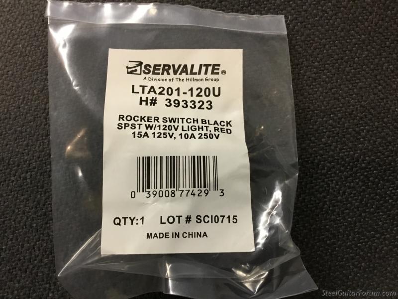
Jack, this was on the web, notice the LTA diagram. Continuity check your switch with an ohm meter to verify the terminals. (A resistance reading will be the lamp connections, no resistance will be on, and infinite resistance will be off).
https://www.carlingtech.com/sites/defau ... agrams.pdf
https://www.carlingtech.com/sites/defau ... agrams.pdf

Looks like it's currently wired as a ground polarity switch, not an on/off switch.
-𝕓𝕆𝕓- (admin) - Robert P. Lee - Recordings - Breathe - D6th - Video
-
Jack Goodson
- Posts: 4773
- Joined: 21 Mar 2005 1:01 am
- Location: new brockton,alabama (deceased)
Switch?
Bill, don,t take this wrong, I am very appreciative of all the help. But I could understand it better if I could see an actual drawing of where the wires connect. According to what I am understanding the ground is correct, the green wire connects to the chassis and from the chassis to the terminal ground, it is not connected to the middle terminal on the switch. My question doe,s the white wire go to the terminal on the strip only or doe,s it still connect to the switch terminal?....thanks jack
-
Jack Goodson
- Posts: 4773
- Joined: 21 Mar 2005 1:01 am
- Location: new brockton,alabama (deceased)
Polarity switch?
bOb, I think you are right, I installed a new switch exactly the way it was hooked up when I got the seat. I used it for about 2/hours with my nv112 amp with no problem. I checked it with a meter and in the off or on position it reads 121 volts. When you turn the switch off the light dims but it still reads 121 volts....I just need to make the switch turn it off and on....thanks jack
-
Bill A. Moore
- Posts: 1310
- Joined: 2 Jul 2007 3:17 pm
- Location: Silver City, New Mexico, USA
-
Jack Goodson
- Posts: 4773
- Joined: 21 Mar 2005 1:01 am
- Location: new brockton,alabama (deceased)
Lta?
Bill. I don,t mean to sound dumb, but I guess I am, I really just need to know where each wire goe,s. I guess that photo don,t exist....thanks jack
-
Bill A. Moore
- Posts: 1310
- Joined: 2 Jul 2007 3:17 pm
- Location: Silver City, New Mexico, USA
The switch has the terminals marked 1-2-3, the LTA diagram shows where each (numbered terminal), goes in the circuit. In your case the load is the power strip. #3 is neutral, (both in and to strip), #1 is hot/black out to the strip, and #2 is the hot/black from the wall/cord.
Double check that #1 makes, and breaks contact with #2 when switched before wiring!
(Note also that it will only work correctly when wired as indicated).
After looking at your pic again, I assume the RH terminal is brass, and should have the white wire, (from the wall) connected to it, as well as the white it already has. The black from the wall should be connected to #2, the middle connector, (with no other connections)! The other white wire is wired to the hot side of the strip, #1 terminal. It will be energized when switched, check it!
-
Jack Goodson
- Posts: 4773
- Joined: 21 Mar 2005 1:01 am
- Location: new brockton,alabama (deceased)
Hookup?
This is the way I have it wired now and it checks 120/volts in the on position and checks 000 in the off position. The only thing is the light stays on. How do I correct that?...thanks jack
-
Bill A. Moore
- Posts: 1310
- Joined: 2 Jul 2007 3:17 pm
- Location: Silver City, New Mexico, USA
The black should be in the center as it is, the white, (on the right of the photo) should go to the RH switch terminal, (if the numbers correspond to the previous post), not to the ground?.
Last edited by Bill A. Moore on 1 Sep 2017 4:09 pm, edited 1 time in total.
-
Jack Goodson
- Posts: 4773
- Joined: 21 Mar 2005 1:01 am
- Location: new brockton,alabama (deceased)
Hookup?
This is the way I have it wired now and it checks 120/volts in the on position and checks 000 in the off position. The only thing is the light stays on. How do I correct that?...thanks jack
-
Jack Goodson
- Posts: 4773
- Joined: 21 Mar 2005 1:01 am
- Location: new brockton,alabama (deceased)
Switch?
Thanks b0b, I have another new switch, will try this right now....jack
-
Jack Goodson
- Posts: 4773
- Joined: 21 Mar 2005 1:01 am
- Location: new brockton,alabama (deceased)
Lost photo?
B0b, I lost the photo that you posted, but I tried it and I get 60v with switch on and the same reading with it off. I went back to double check and cannot find the photo?....thanks jack
Yeah, the photo I posted was wrong so I removed it. Sorry for the confusion.
This is the actual wiring diagram. The light bulb is internal to the switch - it connects between terminals 1 and 3. "LOAD" is the outlet you're connecting it to.

The "E" wires are the black and white wires from the power cord. Doesn't mattr which is which because it's AC. The trick is knowing which terminal is "1" and which is "3".
This is the actual wiring diagram. The light bulb is internal to the switch - it connects between terminals 1 and 3. "LOAD" is the outlet you're connecting it to.
The "E" wires are the black and white wires from the power cord. Doesn't mattr which is which because it's AC. The trick is knowing which terminal is "1" and which is "3".
-𝕓𝕆𝕓- (admin) - Robert P. Lee - Recordings - Breathe - D6th - Video
-
Jack Goodson
- Posts: 4773
- Joined: 21 Mar 2005 1:01 am
- Location: new brockton,alabama (deceased)
Terminal?
One of the terminals on the switch looks like copper, I was assuming it is 3?....thanks jack