| Author |
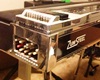
Topic: Session 400 Filter Caps |
Dan Robinson
From:
Colorado, USA
|
 Posted 21 Jun 2015 7:59 pm
 |
|
My Peavey LTD 400 (Session 400 fraternal twin) has extremely bad hum. Replacing the filter capacitors is the most obvious first move.
I am comfortable doing this repair, but parts selection has me worried. Your guidance would be appreciated.
My amp has two aluminum electrolytic capacitors, 5000uF, 55 WVDC, size ~32mm x 100mm. The nearest spec parts I found are 4700uF, 50 WVDC and significantly smaller, 20mm dia. X 40mm long. Will these be OK?Â
Dan |
|
|
|
Stephen Cowell
From:
Round Rock, Texas, USA
|
Posted 21 Jun 2015 9:10 pm
|
|
Never go down in voltage... take the next step up if you can. I'd check the rectifiers first to make sure that they're not having a problem... an open rectifier will give bad hum too. If you see the caps venting or swollen on the end then they're toast. Peavey has replacement parts for this I'm sure.
I have no experience with this vendor, but they appear to have what you need:
http://www.tedss.com/139R502M055AB2A
_________________
Too much junk to list... always getting more. |
|
|
|
Dan Robinson
From:
Colorado, USA
|
Posted 21 Jun 2015 10:26 pm
|
|
| Stephen Cowell wrote: |
| Never go down in voltage... I'd check the rectifiers first... an open rectifier will give bad hum too. If you see the caps venting or swollen on the end then they're toast. |
Right you are, Stephen! Those are great suggestions.
The caps have no visible damage or leaks so the likely culprit is one or more bad diodes (either open or shorted). Easy enough to check, and solid state rectifiers are much less costly than electrolytic capacitors.
We'll soon find out.
Dan |
|
|
|
Cartwright Thompson
|
|
|
|
Ken Fox
From:
Nashville GA USA
|
|
|
|
Howard Montgomery
From:
Topeka, KS US
|
|
|
|
John Limbach
From:
Billings, Montana, USA
|
Posted 22 Jun 2015 10:52 am
|
|
| One of the best additions to my test bench has been an ESR meter which gives the value and condition of electrolytics while still in the circuit. Worth getting one if you work on amps regularly |
|
|
|
Dan Robinson
From:
Colorado, USA
|
Posted 22 Jun 2015 5:12 pm
|
|
Wow, you guys have really given me some exciting ideas! Stephen, Howard, John, Ken thanks for your replies. This project is taking on a new dimension.
Ken, NICE filter caps, 8400uF, 63 WVDC, max temp 105c. They are physically smaller, I think 4 of them would fit. That would mean 33,600uf, vs. 10,000uf originally. Brad Sarno makes a pretty good case for additional capacitance. What do you think of doing that? Have you tried it?
Whatever I put in will get bypassed with some high quality film caps to reduce the noise floor.
I was unaware of all the cool ideas to improve the performance of this amplifier. I haven't used it for some time, and I am pretty stoked!
Stephen, I won't forget to check the rectifiers.
John, I don't have the test gear to check the electrolytics, but given their age, I'm going to replace them regardless how they are performing.
Having taken the chassis out it's maintenance time. Might as well go all in. |
|
|
|
Ken Fox
From:
Nashville GA USA
|
Posted 23 Jun 2015 7:17 am
|
|
| I would stay with 2 of the filters. Too much and it looks like a bad dead short to the power supply when you first turn it on. Hard on the rectifier diodes and even the power transformer |
|
|
|
Dan Robinson
From:
Colorado, USA
|
Posted 23 Jun 2015 7:17 pm
|
|
Thanks, Ken.
Is this as simple as a full-wave/bridge rectifier, electrolytics and bypass caps?
Bleeder resistors?
Anyone have a schematic for the power supply?
Almost ready to put on my tin-foil hat  |
|
|
|
Ken Fox
From:
Nashville GA USA
|
Posted 24 Jun 2015 4:57 am
|
|
 |
|
|
|
Ken Fox
From:
Nashville GA USA
|
Posted 24 Jun 2015 5:01 am
|
|
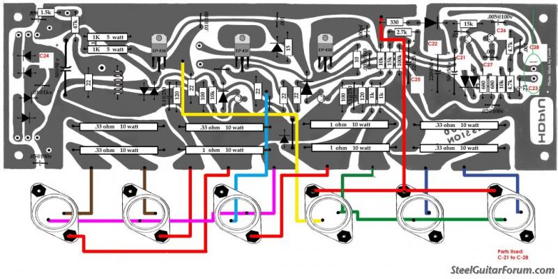
The schematic is slightly altered from the original as far as the filter caps go. I added two more caps at .047 for noise suppression
C29-30 8200/63
C31-32 0.47 |
|
|
|
Dan Robinson
From:
Colorado, USA
|
Posted 24 Jun 2015 8:37 pm
|
|
Ken, thanks so much for the schematic. I will add .047uF film bypass caps, as you suggest.
Rectifier diodes test good. I don't have test gear to check filter caps in-circuit, but they are not shorted. I will replace them, but I'm beginning to think they have not failed.
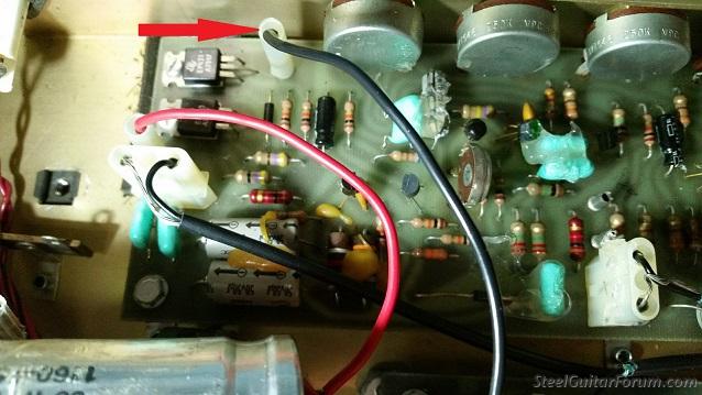
The black wire (see the red arrow) runs from a terminal on one of the filter caps to a pin on the preamp circuit board. The connector was not tight, and possibly not making a connection. Could that be the cause of my hum?
That connector is now securely reattached.
Is there a way to test without risk of frying the power amp or my speaker?
 |
|
|
|
Ken Fox
From:
Nashville GA USA
|
Posted 25 Jun 2015 4:32 am
|
|
| Not sure but have you tried the amp since you tightened that connector? Keep in mind you may have a leaky output transistor and that will cause hum. If it were my amp and did not have the test gear I would send the chassis to Peavey for repair. These power amps are touchy to work on. I have spent a lot of time troubleshooting old LTD and Session 400 amps. All this makes me glad I retired! Some of those amps could drive you nuts! I spent a week chasing down an intermittent in one for a forum member. Finally re-soldered every connection on the power board and fixed it. Had it on a scope with a test signal. It would drop 1/2 of the wave form. About the time I would approach it the amp would start working again. Maddening!!! |
|
|
|
Ken Fox
From:
Nashville GA USA
|
Posted 25 Jun 2015 4:35 am
|
|
| One thing you can safely do is to disconnect the audio signal from the preamp board to the power amp and see if the hum goes away. The Molex connector for the preamp output is to the right on the power amp board, as you face the chassis from the rear. |
|
|
|
Ken Fox
From:
Nashville GA USA
|
Posted 25 Jun 2015 4:43 am
|
|
Here is a layout of the power amp board done by a Forum member. Do not assume that the direction of diodes and transistors is correct! However it has been a great aid for me over the years. The audio connector location is circled in green on the right
 |
|
|
|
Dan Robinson
From:
Colorado, USA
|
Posted 26 Jun 2015 7:02 pm
|
|
My LTD 400 is working again!
I tested just the power amp, as Ken suggested, into a monitor with (cheap) speaker. All good. Re-connected the pre-amp to power amp signal, and it is working.
I may have the reverb Send and Return signals swapped. Otherwise, it's all good.
Thanks for all of your helpful advice.
Dan |
|
|
|
Ken Fox
From:
Nashville GA USA
|
Posted 27 Jun 2015 5:58 am
|
|
| To verify the reverb wires you can disconnect both from the tank first. Turn up the reverb return and tap the end of each wire. The wire that makes a noise goes to the reverb tank's output |
|
|
|
Dan Robinson
From:
Colorado, USA
|
Posted 27 Jun 2015 5:28 pm
|
|
Reverb is working. Seems to me that reverb is not very "deep" on this amp. Or is it just mine? That's OK with me because I don't add much "wet" signal anyway.
This amp spent a lot of time in bars, back when smoking was popular, and permitted. Control pots are noisy, so we'll see how they are after some contact cleaner.
Just 15 minutes playing my Sho-Bud through the amp, but so far, so good. it's a pleasure getting reacquainted with it. |
|
|
|
Craig Baker
From:
Eatonton, Georgia, USA - R.I.P.
|
Posted 27 Jun 2015 6:34 pm
|
|
Ken,
Give me a good thrashing if I am wrong, but in my opinion, the amount of in-rush current the filter caps draw at turn-on make them no place for molex connectors.
Thrash away Ken.
Craig Baker 706-485-8792
cmbakerelectronics@gmail.com
C.M. Baker Electronics
P.O. Box 3965
Eatonton, GA 31024
_________________
"Make America Great Again". . . The Only Country With Dream After Its Name. |
|
|
|
Ken Fox
From:
Nashville GA USA
|
Posted 28 Jun 2015 3:20 pm
|
|
| Never been a fan of Molex connectors but I suspect they do better in the power supply than in low level signal circuits. Never really had an issue with them in the powe supply applications. Still I prefer hard wired, soldered connections over mechanical connectors. |
|
|
|
Dan Robinson
From:
Colorado, USA
|
Posted 29 Jun 2015 10:32 pm
|
|
I don't know enough to have an opinion about molex connectors. But I'm a quick enough study to know I hate loose connectors.
New filter and film bypass caps are ordered. I can hear some static-like noise when I strike my strings. If the new power supply caps don't resolve the noise then I'll check connectors. I have no objection to replacing certain connectors with good solder joints.
Upgrading some ceramic signal caps with better components (film caps?) is possible future project. But for now I just need it to be as quiet as its design permits. |
|
|
|
Lane Gray
From:
Topeka, KS
|
Posted 30 Jun 2015 8:12 am
|
|
If you hear static when you strike the strings, I'd first look at loose connection on guitar and maybe lower the pickup, in case you're overdriving the input.
_________________
2 pedal steels, a lapStrat, and an 8-string Dobro (and 3 ukes)
More amps than guitars, and not many effects |
|
|
|